
Building Stuff...woot
2018-11-29
KiCad, Generalization and Workflow
ugh the preceding document is the culmination of a set of rants and thought about PCB design software for some; there's a TLDR at the bottom. I ran out of steam writing it eventually but some of the ideas with work flow are kind of interesting. I'm going to post the bulk of it on kicad forums to see if anything will come of it there. If it doesn't maybe it's time to take a stab at the kicad source.

2017-07-11
Spiral Multiplier Nixie Clock
First I would like to devote this post to all the engineers that put their time into the creation of the modern printed circuit board and namely Pail Eisler who apparently is the inventor. Because I decided to point to point solder this project together and I am never doing that again, even if it is 'small' and all through hole, just like this dumb clock . When a 40 pin fan out is required there are just so many connections involved, stripping every wire, hand soldering each joint. I did this originally because I wasn't in the mood to route and wait for a board, that was a horrible idea. Boards get routed by hand threading wires and soldering them in place or they get routed on a computer; one method is infinitely more painful for a even a moderate number of components.

The clock is a bit of a Rubegoldberg machine but really it didn't have to be this way. All of the pain and annoyance of this particular project are entirely self inflicted, but once everything was debugged everything seemed to work as intended and nothing exploded of it's own accord. I helped it out with that a few times though.
That being said I've made a nixie clock. It powers the tubes from a spiral multiplier topology; if you're wondering what that is, see my last post cause I made it up and haven't seen it anywhere else. In this particular case it is a 4s3p multiplier array. This one in particular has 3 strands in parallel because it was easy to make a ring oscillator to drive them all out of phase, there is no other particular reason for it. Future designs could be done in a much more efficient compact fashion, that being said despite being an overly complex machine, it works. The FETs don't get hot at all, the caps are stressed a lot voltage wise but that was somewhat intentional and a bit of an experiment and you wouldn't notice if any of the supply was actually turned on and there's no noticeable noise, really nothing is being worked hard power wise.
The build up of the system went in a piece wise fashion. Multiplier was built up first, mainly because it was easy to free hand and capable of being treated as an independent lump with only a few connections.
This assembly really was the painful part. The speed of bending each wire into joint and soldering it was excruciating.
After making the multiplier came the PWM /controls set up. Since the system is open loop so there really aren't any controls to speak of. Controls would be logical for almost any other implementation, however the input to the multiplier system is a 15V regulated wall wart, and the multiplier itself is effectively a fancy step-up with constant load. So load variation and line variation are not issues. If people had the potential to plug in other regulators, or if the system were powered straight from the line regulation would be more of a concern. After finishing the inverter some basic testing was possible:
The multiplier is hiding in the far right f this picture, the inverter is front and center. Controls/ inverter are dead center. The Red wire is the HV into the tube. Output voltage from the supply can reach >200V with no load, but rides at 170V under load with all of the nixies. The voltage over the tube (that's on the multimeter) sits right at where the data sheets says it should site ~140V and in this test there was a resistor doing the current limiting for the tube. There are probably some resonant effects playing into the output voltage stability that I haven't characterized. The system output voltage is surprisingly invariant under different loads.
Feed back can always be added but, it wasn't needed and time, cost, effort...laziness efficiency. The heart of the 'controls' is a 3-inverter ring oscillator. It generates three 120 degree out of phase triangle waves. These go to the inputs of three comparators that output three square waves. AND THEN they go to a set of inverters that flip half the PWM signals, add dead time then buffer the outputs. This was all done using 74XX14's and passives/diodes, too many of them. Really the more proper way to implement this set up effort would be a PLD or microcontroller, it would greatly reduce parts count and over all cost of this endeavor; since only one of this particular object was getting made and didn't want to futz with tool chains and microcontrollers. It seemed like less trouble to do it in a very brain dead way using 74 logic with this circuit:
Six of these circuits were used, one for each pwm channel. They invert each wave and lop off the front of each pulse. Half of the delayed signals are inverted again. This makes it so there will be dead time between each pwming pair; and no shoot through between the hi and lo switches in each bridge.
The duty cycle is constant around 50% and the system is run approximately resonantly at 47ish kHz.


The clock is a bit of a Rubegoldberg machine but really it didn't have to be this way. All of the pain and annoyance of this particular project are entirely self inflicted, but once everything was debugged everything seemed to work as intended and nothing exploded of it's own accord. I helped it out with that a few times though.
That being said I've made a nixie clock. It powers the tubes from a spiral multiplier topology; if you're wondering what that is, see my last post cause I made it up and haven't seen it anywhere else. In this particular case it is a 4s3p multiplier array. This one in particular has 3 strands in parallel because it was easy to make a ring oscillator to drive them all out of phase, there is no other particular reason for it. Future designs could be done in a much more efficient compact fashion, that being said despite being an overly complex machine, it works. The FETs don't get hot at all, the caps are stressed a lot voltage wise but that was somewhat intentional and a bit of an experiment and you wouldn't notice if any of the supply was actually turned on and there's no noticeable noise, really nothing is being worked hard power wise.
The build up of the system went in a piece wise fashion. Multiplier was built up first, mainly because it was easy to free hand and capable of being treated as an independent lump with only a few connections.
 |
| First, assembly of the multiplier stack |
 |
| then the controllllls and inverter |
 |
| mooore soooooldering controls and inverter |
After making the multiplier came the PWM /controls set up. Since the system is open loop so there really aren't any controls to speak of. Controls would be logical for almost any other implementation, however the input to the multiplier system is a 15V regulated wall wart, and the multiplier itself is effectively a fancy step-up with constant load. So load variation and line variation are not issues. If people had the potential to plug in other regulators, or if the system were powered straight from the line regulation would be more of a concern. After finishing the inverter some basic testing was possible:
 |
| Single tube test of multiplier |
The multiplier is hiding in the far right f this picture, the inverter is front and center. Controls/ inverter are dead center. The Red wire is the HV into the tube. Output voltage from the supply can reach >200V with no load, but rides at 170V under load with all of the nixies. The voltage over the tube (that's on the multimeter) sits right at where the data sheets says it should site ~140V and in this test there was a resistor doing the current limiting for the tube. There are probably some resonant effects playing into the output voltage stability that I haven't characterized. The system output voltage is surprisingly invariant under different loads.
Feed back can always be added but, it wasn't needed and time, cost, effort...
 |
| It nibbles off the front end of the wave form and inverts it |
Six of these circuits were used, one for each pwm channel. They invert each wave and lop off the front of each pulse. Half of the delayed signals are inverted again. This makes it so there will be dead time between each pwming pair; and no shoot through between the hi and lo switches in each bridge.
 |
| Example of dead-time between falling and rising wave forms there is indeed something weird with the upperr wave form but I can't actually remember what is was anymore. |
 |
| Pretty Glowy Tubes |
The real regrets in this project (besides the assembly) comes with implementation of the digital controls for the clock. The power electronics were really the less obnoxious part, maybe that says something about my skill set, but at least I know why this part of the implementation was stupid and had an initial reason for the subsequent masochism. The digital controls comprises a clock chip, microcontroller, and load of stupid that fans out the microcontroller to all of the HV outputs. The clock chip is one of the cheapest through hole clock chips available the DS1307 by maxim. It's a pretty simple object and uses I2C to communicate with the microcontroller, this helps it keep actual accurate time with a crystal. One thing to note is that you can just buy a micro with a real time clock included, but this gave me an excuse to learn I2C. The microcontroller was an arduino, because as far as needing software or fancy programmers they represent an absolute minimum of effort and are acceptable for an application that doesn't have any respectable performance criteria.
`

For the fanout, eight digital outputs of the microcontroller are used to control all of the nixie tubes; effectively an 8 to 40 expansion as one switch is required to control each digit on each nixie tube. The size of the fanout was really somewhat annoying. The tubes have a comma digit to each side of the number that were left unused in this application. One thing to note is that technically access to all digits in each tube is not required; this was going to be a 24 hour clock making it so that only 3/10 available digits were used on the 10's hours digit...actually you could get away with 2/10 on the last digit if it was blanked instead of showing a '0' which would let you do everything with 32 outputs. But you could definitely do a 12 hour clock with 32 outputs. I'm getting away from crapping on the the current design which should have been implemented as a set of shift registers (or a single shift register). The fanout setup in the current system that was done for the following reasons:
A. to teach someone about human time vs. electrical time.
B. To have them consider the boundaries of what is required vs. what is optimal.
C. For some short amount of time it seemed like a fun idea.
A and B still seem like valid reasons. the fanout was set up as two channels of BCD, 4-digital pins of the micro went to each channel feeding one BCD which then fed 2 more BCDs from its 10 valid outputs. One set of three BCD for the minutes, another set for the hours.
This encoding and conversion was just annoying to deal with. There is one aspect missing here, because the first layer of the fanout can only select one output at a time, it can't produce all the combinations required on the output BCD's. To do this the following circuit was used:
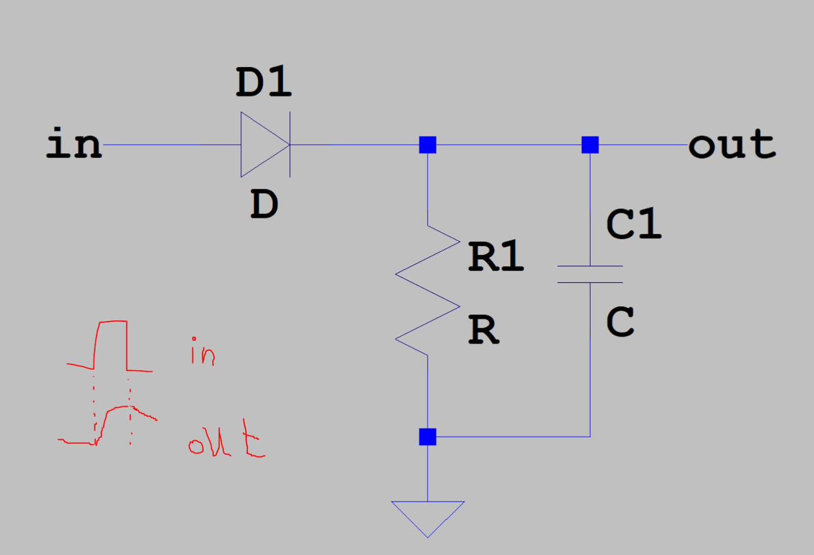
On the input of each second layer BCD the voltage is held by the RC. Then refreshed before the RC runs out. This allows the first layer BCD to turn on an arbitrary set of inputs to the second layer as long as its quick enough, which is pretty easy as long as the RC time constant is long enough. It's dumb but it seemed to work pretty well.
Finally after all these shenanigans the output of each second level BCD goes to a high voltage transistor for switching each digit on the tubes. This whole ordeal was far more trouble than it needed to be. But whatever, the clock clocks, and damn if those glowing tubes don't look pretty.
 |
| mmm glowy |
I bought a box to put the clock in as well, because not shocking people is important. That's less exciting, but I might make a post about it.
What's exciting though is I've already started on my next nixie venture and I'm most of the way done with it. It uses it's own silly topology and does not use any switching regulators to run off of the line, so you will be seeing a post about that.
2016-10-30
On Voltage Multipliers, Spiral Multipliers
Of late I have been thinking about voltage multipliers for a variety of reasons. One of which was that I wanted to build a nixie clock and it seemed like an excellent excuse to over design something which could be far simpler. This circuit is what I call a spiral multiplier and I'll get into the details of it in a bit. A friend wanted to learn something about electronics when deciding to do this and this circuit seemed like an interesting way to learn about a variety of concepts and component properties at the same time. The tubes I planned on using could 'just' be powered off of rectified wall voltage with some resistors and filtering, but for safety's sake its nice not to power things with up to 170V and a kW of power oomph. It also makes the problem more interesting stepping the low voltage up to the higher voltage.
I somewhat arbitrarily decided to take 15V and turn it into; $\gt$ 140V at full load (minimum holding voltage of the tubes) to power the nixie tubes. Really the tubes need 170V to spark over according to the data sheet. The decision to go with a multiplier was partly motivated by not being very pleased by many of the transformers I saw available. But realistically speaking using a transformer would be the practical thing to do in this besides powering the tubes off wall power; but where is the fun in that?
Lots of things are technically feasible in this case since it is a low power supply and don't care about the efficiency of a nixie clock as long as heat sinks aren't required.
Which brings about applicable designs and the aforementioned spiral multiplier:
The body of the multiplier (everything on the upper left side of the schematic) is the part pertaining to this post. It is all about the caps and the diodes.
The above traces are for a controlled output set point, if left to its own devices the multiplier will go to a much higher voltage at full power. Open loop the circuit went up to ~200V. The above schematic doesn't look much like a spiral. Below is a topological approximation of the spice simulation circuit which most importantly looks like a spiral:
This spiral topology represents a combo of two basic multiplier types the parallel and series style multipliers. Each 'spoke' coming from the center of the spiral is topologically identical to a capacitor string (or stack) found in a series multiplier while each round of the spiral is analogous to travelling up a parallel multiplier. The spiral multiplier of some arbitrary number of rounds $ \geq 1$ and spokes $ \geq 2$ is a generalization of the series and parallel multipliers where either one represents a base case; spiral circuits similar to the full wave cockcroft-walton multiplier can also be constructed (look at the wikipedia page).
Backing up to the big picture:
Diode based voltage multipliers have been around a very long time like almost a 100ish years according to the wikipedia. If you aren't familiar with voltage multipliers they do as the name implies and take a smaller magnitude (AC) voltage and turn it into a larger magnitude (DC) voltage of some multiple of the AC amplitude (in the ideal case).
Fundamentally multipliers are built up of capacitor coupled nodes with some diodes slapped on. This forms a network of peak detectors, each peak detector takes the peak AC voltage through a diode and deposits it on to a capacitor. This forms a 'unit pump':
In the unit pump, if $Vac$ dips below $Vin$ (by a diode drop), charge is deposited onto capacitor C1. $Vo = Vin-Vd$ when Vac swings positive you get: $\hat{Vo} = \hat{Vac} + Vc$. The capacitor maintains a DC bias from the AC wave form injected through Vac boosting Vo.
These unit pumps are chained in various formats to form different types of multipliers.
Traditional diode multipliers tend to break down into two forms series/cascade multipliers and dickson/parallel multipliers which are generally treated as two fundamentally different approaches.
A series multiplier is driven from a power source a coupled up through all the subsequent stages whereas in a parallel multiplier the power source is directly coupled through a capacitor to a node in a chain of diodes. The difference in the power coupling has interesting effects. The source impedance of a series multiplier increases as the cube of the number of stages; this is an incredible pain sometimes. However it conveniently grades the voltage up the whole multiplier stack so you only have to couple power into the low voltage end and all of your components can be of a lower voltage rating.
A parallel multiplier doesn't have that $n^{3}$ impedance issue but requires direct energy couplings to the high voltage end resulting in a fair amount of energy storage (for the same F capacitors) and it doesn't grade the voltage with the capacitors. Note the similarity between the above series example and the below parallel example
The voltage increases by the Vpp AC voltage with every pumping node and gets filtered to some extent by every filtering node. Both multipliers have the same AC source and reach the similar output voltage.
Both are special in their own way. However both also only represent usage of the unit pump in one 'dimension'. The spiral multiplier is the cross of the two defining a a series/parallel matrix of unit cells. I haven't actually analyzed the topology in detail to see if there are any fundamentally better properties, but it seems like a fun experiment. Analytical awesomeness can be postponed.
Here is an example of a spiral multiplier.It is effectively 2 parallel multipliers (each consisting of 4 unit cells) stacked on top of each other. The output of the lower one feeding the input of the higher voltage one. Really you could string $n$ of them together on top of each other and feed the bias of each multiplier one into the beginning of the next. Alternately it can be seen as taking $M$ series capacitor strings and setting them side by side, linking up each DC biased section in the proper format. 2 rounds of a 4 spoke spiral. How it is viewed is a somewhat arbitrary exercise imo. that could be argued multiple ways depending on the nuances of a particular system. Every circuit is what it does. Note that in the initial 4x3 multiplier at the top of the post I didn't even bother with a filter string in the body of the multiplier, just an output peak detector to mellow the output ripple.
I'm tired of typing about this right now and feel like it'll turn into a thesis if I keep going. The spiral multiplier concept seemed like an interesting one and there are a couple expansions of the topology that I can think of, involving peak detector loops over filter caps and gaming the phasing of the pump sources.
toodloo
I somewhat arbitrarily decided to take 15V and turn it into; $\gt$ 140V at full load (minimum holding voltage of the tubes) to power the nixie tubes. Really the tubes need 170V to spark over according to the data sheet. The decision to go with a multiplier was partly motivated by not being very pleased by many of the transformers I saw available. But realistically speaking using a transformer would be the practical thing to do in this besides powering the tubes off wall power; but where is the fun in that?
Lots of things are technically feasible in this case since it is a low power supply and don't care about the efficiency of a nixie clock as long as heat sinks aren't required.
Which brings about applicable designs and the aforementioned spiral multiplier:
 |
| 4 series 3 parallel Spiral Multiplier, peak detector on output as filter. |
 |
| Output Voltage green (set a lower control voltage), control feed back: red, pink is the gate voltage on the feed back transistor. |
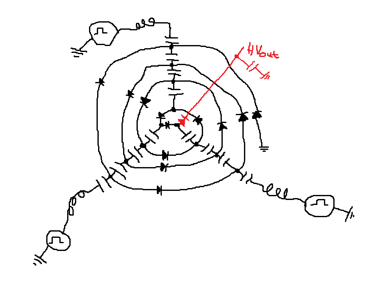 |
| Spiral style schematic of the nixie multiplier, it has a filtering peak detector on the output. |
This spiral topology represents a combo of two basic multiplier types the parallel and series style multipliers. Each 'spoke' coming from the center of the spiral is topologically identical to a capacitor string (or stack) found in a series multiplier while each round of the spiral is analogous to travelling up a parallel multiplier. The spiral multiplier of some arbitrary number of rounds $ \geq 1$ and spokes $ \geq 2$ is a generalization of the series and parallel multipliers where either one represents a base case; spiral circuits similar to the full wave cockcroft-walton multiplier can also be constructed (look at the wikipedia page).
Backing up to the big picture:
Diode based voltage multipliers have been around a very long time like almost a 100ish years according to the wikipedia. If you aren't familiar with voltage multipliers they do as the name implies and take a smaller magnitude (AC) voltage and turn it into a larger magnitude (DC) voltage of some multiple of the AC amplitude (in the ideal case).
Fundamentally multipliers are built up of capacitor coupled nodes with some diodes slapped on. This forms a network of peak detectors, each peak detector takes the peak AC voltage through a diode and deposits it on to a capacitor. This forms a 'unit pump':
 |
| The unit cell of a multiplier |
In the unit pump, if $Vac$ dips below $Vin$ (by a diode drop), charge is deposited onto capacitor C1. $Vo = Vin-Vd$ when Vac swings positive you get: $\hat{Vo} = \hat{Vac} + Vc$. The capacitor maintains a DC bias from the AC wave form injected through Vac boosting Vo.
These unit pumps are chained in various formats to form different types of multipliers.
A series multiplier is driven from a power source a coupled up through all the subsequent stages whereas in a parallel multiplier the power source is directly coupled through a capacitor to a node in a chain of diodes. The difference in the power coupling has interesting effects. The source impedance of a series multiplier increases as the cube of the number of stages; this is an incredible pain sometimes. However it conveniently grades the voltage up the whole multiplier stack so you only have to couple power into the low voltage end and all of your components can be of a lower voltage rating.
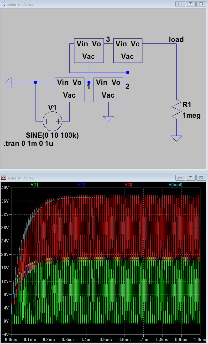 |
| Series multiplier, takes 20Vpp input, 40Vmax output |
A parallel multiplier doesn't have that $n^{3}$ impedance issue but requires direct energy couplings to the high voltage end resulting in a fair amount of energy storage (for the same F capacitors) and it doesn't grade the voltage with the capacitors. Note the similarity between the above series example and the below parallel example
 |
| Parallel multiplier, takes 20Vpp input, 40Vmax output |
The voltage increases by the Vpp AC voltage with every pumping node and gets filtered to some extent by every filtering node. Both multipliers have the same AC source and reach the similar output voltage.
Both are special in their own way. However both also only represent usage of the unit pump in one 'dimension'. The spiral multiplier is the cross of the two defining a a series/parallel matrix of unit cells. I haven't actually analyzed the topology in detail to see if there are any fundamentally better properties, but it seems like a fun experiment. Analytical awesomeness can be postponed.
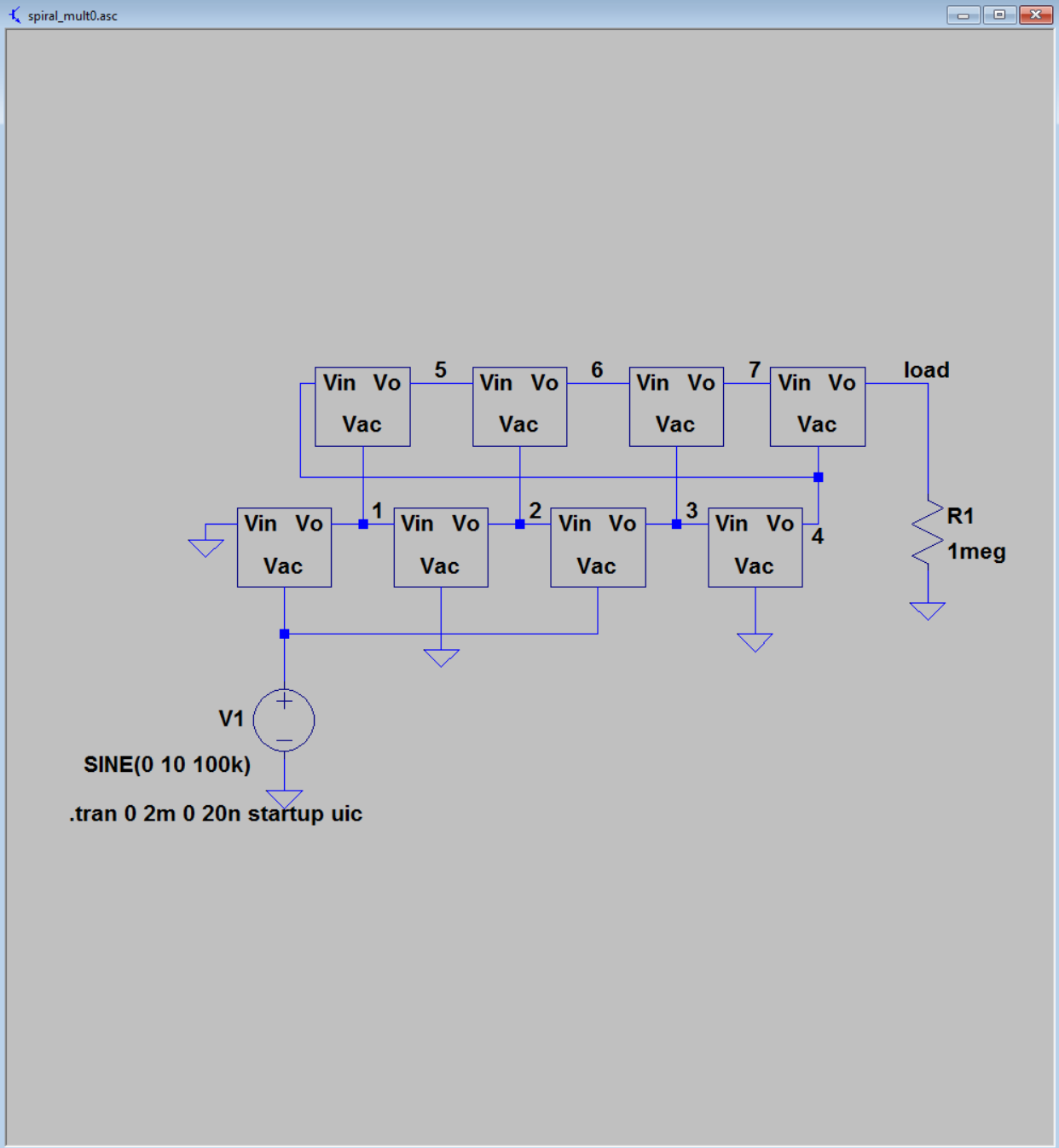 |
| A 2x4 Spiral Multiplier |
 |
| 2x4 Wave forms with tiny load |
Here is an example of a spiral multiplier.It is effectively 2 parallel multipliers (each consisting of 4 unit cells) stacked on top of each other. The output of the lower one feeding the input of the higher voltage one. Really you could string $n$ of them together on top of each other and feed the bias of each multiplier one into the beginning of the next. Alternately it can be seen as taking $M$ series capacitor strings and setting them side by side, linking up each DC biased section in the proper format. 2 rounds of a 4 spoke spiral. How it is viewed is a somewhat arbitrary exercise imo. that could be argued multiple ways depending on the nuances of a particular system. Every circuit is what it does. Note that in the initial 4x3 multiplier at the top of the post I didn't even bother with a filter string in the body of the multiplier, just an output peak detector to mellow the output ripple.
I'm tired of typing about this right now and feel like it'll turn into a thesis if I keep going. The spiral multiplier concept seemed like an interesting one and there are a couple expansions of the topology that I can think of, involving peak detector loops over filter caps and gaming the phasing of the pump sources.
toodloo
2015-10-07
The Derp Driver
Everyonce in a while I get a really dumb idea behold the derp drive:


Derp Drive 99% 'what if?', 1% something else
So one day I decided that I wanted to make a cutesy little bench top supply because bench top supplies are balls expensive. I'm going to talk about the rest of this venture at a later date. But today I will talk for too long about the gate drive and how it is for the most part an exercise in curiosity.
Imagine for a moment that you wanted to switch a supply at 500kHz on a full bridge in an odd synchronous fashion. Your are strapped by cash and need synchronous rectification on the output because you're going to be dealing with high current and low voltages. You also want the output floating because if the output floats that's handy it means you can have +V or -V or stacked or paralleled if the outputs can share current.
But doing synchronous rectification requires gate drives, some weird boot strapping some form of isolation. If gate drives go in that means an auxiliary floating set of voltage rails for the drivers and some sort of sensing the voltage state which means chips and rails and money and stuff.
It would be nice if all the switches were driven by floating things, you know kinda like a transformer.
But transformers cost money they are big and slow and inductive... but that is a fallacy. Lots of fast things use transformers for signals, pulse transformers are things, USB uses transformers, ETHERNET uses transformers. Ain't nobody calling my gigabits slow. There are some highly legitimate reasons why signals like usb and ethernet utilize magnetic coupling for signals:
- It can be isolated electrically. My laptop could sit at a completely different potential than your laptop, powered by batteries or off the line and they could still yarble at one another over an CAT5e cable thanks tot he awesomeness that is transformers.
- A local return path/ reference. Any signal sent out needs to be with reference to something and have a return path and to be a fast signal inductance needs to be minimized. This is why PCIe, usb, ethernet, SATA and ect. are all differential pairs for high speed signalling. Transformers by nature create a differential voltage source. As a statement of Gauss's law and conservation of charge they must create a + and relative - to maintain the E field flux but I'm going off on a limb. The important bit is that by creation of a differential signal a return path exists that does not necessarily need to be referenced to ground or anything in particular besides the other end of the wire in the transformer.
- You can have common modes impedance without differential mode impedance. if your output if flapping around a some voltage this can help keep noise from getting into the primary side of the circuit. because transformers aren't perfect and they have some amount of capacitance going from the secondary to primary side.
Transformers are pretty nifty for a variety of reasons, but they have their limitations. That being said in the system of this gate drive I am worried about the volt-seconds that the cores will be able to withstand before saturating.
Once the cores become saturated the primary becomes decoupled from the secondary in at least one direction and the ability to keep the switches in a specific state compromised (to some extent). The ethernet transformers I have seen largely don't come with a primary volt-second spec. However the ethernet transformers I have seen seem to posses a magnetizing inductance of ~300uH which I thought was surprisingly high, and I think puts the idea of the gate driver on the edge of potentially acceptable/ practical.
As far as practical implementations go all of the ethernet transformers are center tapped on the primary and secondary side. By running a push-pull converter using the primary centertap the transformer is a 2:1 step up. This allows you to effectively drive a fet using logic level voltages, once you get above 10V on the gate of a FET the reduction in Rds on is generally marginal. I think the advantage this system would get from running at higher voltages is the faster turn on time of the switch but once the switches are on it won't matter much.
This brings into discussion a few things which I have marginally modeled in spice. What limits the turn on speed of the device? Like I got a voltage source with some impedance. The switches require some base line amount of voltage to turn on. The FET gates are a derpy capacitor, in order to turn on the switch requires some amount of charge slapped on the gate which roughly translates into a given amount of energy (roughly). The goal of a fast gate driver must be to deposit that energy onto the gate as a fast as possible. Any impedance between your roughly ideal voltage source of a decoupling cap which is hopefully sized significantly larger than your gate capacitance otherwise what the fuck are you doing, will restrict the flow of power. There were many many assumptions made in that last sentence.
But what it boils down to is what is throttling the current? resistance or inductance? with a transformer inductance can be a severe issue at high frequency. Even if the fundamental frequency of the switching isn't that fast what is important its about the rise time of the gates voltage waveform. The long the turn on the longer the losses and that what I care about reducing.
But holy fuck the post is longer than I expected and I'm just glossing over things. may I'll post the spice sim next post.
But holy fuck the post is longer than I expected and I'm just glossing over things. may I'll post the spice sim next post.
2015-09-27
On the Mother board and stepper carriers
The mother board I was referring to in my last post got made and seems roughly functional.
Despite me screwing up the stepper driver to some extent.
The mother board should be able to interface to six of the stepper carriers as soon as I produce a stepper carrier that isn't inherently screwed up ...besides the first round of stepper carriers which worked just fine ironically.Tango 1.1.3 has some dumb issues as i turns out not all 780x devices in the same packages have the same pin out and I was playing a bit fast and loose with the foot prints and mixed up the 5V with the ctl power in on the 5V regulator I was using. This may have resulted in burning out the gate driver chip immediately since I wasn't able to coax any PWMing out of the tango driver after fixing the foot print mess up. Le sigh.
Time to populate/kludge another carrier board. If this time round I get the board built up right and touble shoot it it will be pretty exciting to have a board carrier for so many boards. It will make a nice test platform.
The mother board is laid out in a fashion that allows for n arduino mini or some other equivalent micro to be mounted onto the board and have its outputs connect to all the varirious driver boards through the parallel busses laid out on the mother board. There are up to ~8 accessible signals on each bus/ for each driver board (the GND/SIG/GND/SIG/GND/SIG traces reffered to in the last post). This was intended to leave the future possibilities open. Currently the stepper driver would only use 2 signals/ driver leaving lots of possibilities.
Hopefully I'll get something done on the stepper fron again soon. I've been a bit distracted by other electronics and that whole having a job thing.
Despite me screwing up the stepper driver to some extent.
The mother board should be able to interface to six of the stepper carriers as soon as I produce a stepper carrier that isn't inherently screwed up ...besides the first round of stepper carriers which worked just fine ironically.Tango 1.1.3 has some dumb issues as i turns out not all 780x devices in the same packages have the same pin out and I was playing a bit fast and loose with the foot prints and mixed up the 5V with the ctl power in on the 5V regulator I was using. This may have resulted in burning out the gate driver chip immediately since I wasn't able to coax any PWMing out of the tango driver after fixing the foot print mess up. Le sigh.
Time to populate/kludge another carrier board. If this time round I get the board built up right and touble shoot it it will be pretty exciting to have a board carrier for so many boards. It will make a nice test platform.
The mother board is laid out in a fashion that allows for n arduino mini or some other equivalent micro to be mounted onto the board and have its outputs connect to all the varirious driver boards through the parallel busses laid out on the mother board. There are up to ~8 accessible signals on each bus/ for each driver board (the GND/SIG/GND/SIG/GND/SIG traces reffered to in the last post). This was intended to leave the future possibilities open. Currently the stepper driver would only use 2 signals/ driver leaving lots of possibilities.
Hopefully I'll get something done on the stepper fron again soon. I've been a bit distracted by other electronics and that whole having a job thing.
2014-03-16
Motherboard/ Driver carrier board preview
Here is a preview/test route of the motherboard to hold the tango drivers:

The traces go kind of like this:
gnd, signal, gnd, signal, gnd, signal, gnd, signal, gnd, signal, gnd, signal, gnd, signal, gnd, signal, gnd, signal, gnd, signal, gnd, signal, gnd, signal, gnd, signal, gnd, signal, gnd, signal, gnd, signal, gnd, signal, gnd, signal, gnd, signal, gnd, signal, gnd, signal, gnd, signal, gnd, signal, gnd, signal, gnd, signal, gnd, signal, gnd, signal, gnd, signal, gnd, signal, gnd, signal, gnd, signal, gnd, signal, gnd, signal, gnd, signal, gnd, signal, gnd, signal, gnd, signal, gnd, signal, gnd, signal, gnd, signal, gnd, signal, gnd, signal, gnd, signal, gnd, signal, gnd, signal, gnd, signal, gnd, signal, gnd, signal, gnd, signal, gnd, signal, gnd, signal, gnd, signal, gnd, signal, gnd, signal, gnd, signal, gnd, signal, gnd, signal, gnd, signal, gnd, signal, gnd, signal, gnd, signal, gnd, signal, gnd, signal, gnd, signal, gnd, signal, gnd, signal, gnd, signal, gnd, signal, gnd, signal, gnd, signal, gnd, signal, gnd, signal, gnd, signal, gnd, signal, gnd
I'll talk about why in my next post and some adjustments I made to the tango board before sending it to the fab, I need sleep.
The traces go kind of like this:
gnd, signal, gnd, signal, gnd, signal, gnd, signal, gnd, signal, gnd, signal, gnd, signal, gnd, signal, gnd, signal, gnd, signal, gnd, signal, gnd, signal, gnd, signal, gnd, signal, gnd, signal, gnd, signal, gnd, signal, gnd, signal, gnd, signal, gnd, signal, gnd, signal, gnd, signal, gnd, signal, gnd, signal, gnd, signal, gnd, signal, gnd, signal, gnd, signal, gnd, signal, gnd, signal, gnd, signal, gnd, signal, gnd, signal, gnd, signal, gnd, signal, gnd, signal, gnd, signal, gnd, signal, gnd, signal, gnd, signal, gnd, signal, gnd, signal, gnd, signal, gnd, signal, gnd, signal, gnd, signal, gnd, signal, gnd, signal, gnd, signal, gnd, signal, gnd, signal, gnd, signal, gnd, signal, gnd, signal, gnd, signal, gnd, signal, gnd, signal, gnd, signal, gnd, signal, gnd, signal, gnd, signal, gnd, signal, gnd, signal, gnd, signal, gnd, signal, gnd, signal, gnd, signal, gnd, signal, gnd, signal, gnd, signal, gnd, signal, gnd, signal, gnd, signal, gnd, signal, gnd
I'll talk about why in my next post and some adjustments I made to the tango board before sending it to the fab, I need sleep.
2014-03-04
Stepper Driver v1.1.3: tango: ready for manufacturing
So the next iteration of the stepper driver for the millathe has been laid out. It it fixes a few quirks on the waltz board such as some mussed up foot prints and lack of labelling on the dip switches. Also it takes up much less copper are and uses a different card edge connector, actually made to fit a 64 pin PCIe connector. Why? Because as it turns out PCIe connectors are
1. apparently way cheaper than other car edge connectors mostly likely because they're made in stupid quantities.
2. capable of carrying fairly high currents 1A+/pin*64 pins = more amps than a board this size should carry.
3. It's metric and has a 1mm pin pitch, the 1mm pitch is nice and small shrinking the space the signals take up vs .1" pitch. Also I abhore standard units and .1" spacing is the bane of my existance.
4. A 2x32 pin connector is just about the right size for this board.
That being said lets take a look at this board, behold Tango:
You might have noticed I did not skimp on the copper. all of the large current carrying traces (motor voltage, pwrgnd, all motor out/inputs) are straight up polygons. I figured there really was no harm in increasing the power sinking capabilities of the board. Actually there is some harm assembly will be slightly more painful, there are no thermals on this board, it is made to be soldered in an oven or with the aid of a hot air gun. The terminal connectors on the left hand side of the board just won't go on with out the soldering iron turned to the max other wise. However besides that one downside there isn't much of a case against using all of the power side copper that is is available in this scenario. I would rather maximise dissipative capabilities and minimize dissipation.
As far as gate driving is concerned this circuit is still using the original A4989 output as the driver despite (in my opinion) it's relative low current output in the 10's to -barley 100's of mA range for maybe a 20Ohmish resistive values on the gate output. One this I might want to experiment with in this scenario is the ringing effects of an under damped gate vs. the losses from turning on slower due to the damped circuit. In order to minimize inductance ( and therefore overshoot/ringing) in the system each gate drive trace was routed in a pair with a trace going to the source of it's corresponding mosfet, similar to a parallel port matching each signal is matched with a return ground for lower inductance. With the smaller loop it will also lower noise from inductive coupling from the currents on the power side of the board.
In comparison with the last stepper board this one boasts a larger volume pair of decoupling caps for the motors, they could probably be smaller and they take up an ass load of room where assload is like 1cm^2 each... maybe not huge but for this board that is a big component. If you put a rectangle arround the board there is around 35cm^2 of area on this board making them take up around roughly 5.7% of all possible physical space.
But on the plus side with the increased size of the capacitors allows me to use ones with higher voltage ratings/ capacitance ratings. That was a major limiting factor of the driver last time. Now the main voltage limitation is the power mostfets.
So about them
mosfets. this time around going with the DPAK FDD8778 again same fet as last time. One of the main reasons I'm going with it again is it's relatively low gate charge and reasonable on resistance (14mOhm@25C/10vgs). When operating at higher voltages my calculations say that according to the equation:
\\[ Psw = I_{ds} V_{ds} /2(Q/ I_{hl} +Q) \\
but apparent the latex add in I have isnt working... I'll edit this bit later.
Either way the important take away is this equation:
Psw = Ids*Vds/2*Qg*(1/ihl+1/ilh)
It represents the switching power losses occuring in the system.
As far as numbers go for me.
Vds=25V
Ids = 10A
Qg(that I care about) ~ 9nC
ihl/ilh~100mA with a complete short on the driver (I'm going to look at how low a value of gate resistors this circuit can get away with)
f=some weird poop
Now the stepper frequency, it has a linear correlation with your switching losses and is therefore important highly dependent on your control method. In the tango driver, the A4989 controller provides a hysteretic-constant off time current control method. A hysteretic controllers are also called bang-bang controllers, they are not constant frequency and the dependent on the system load. Often thermostats contol temperature using a bang-bang controller. Generally with a hysteretic controller you have a high limit and a low limit, when the output sense is below the lower limit the controller turns on the power full blast, then once the out put sense reaches the higher limit it turns off the power.
Example:
Your thermostat is set to 70 with +/-5 degree limits on the temperature, the temperature is dropping in your house because it's winter and cold outside. The temperature in your house drops to 65. The thermostat senses this and cranks on the heater; depending how large your house is and how powerful the heater affects how quickly your house heats up. Regardless of how long it takes, your heater is going to try it's damnedest to heat up that house as fast as it possibly can. Once your house is 75 degree the thermostat shuts off the the heater and your house begins to cool again. This cycle then repeats.
In the control of the stepper motor the controller is similar, but rather than having a lower limit it just turns the controller off for a fixed time. With this controller, the controller clock is 4MHz (set through a resistor) and the fixed off time is 87 clock cycles. This sets an upper limit pwm frequency of ~46kHz, giving us a decay time of 21.75microseconds. The load dynamics decide how long the on-period will be. The load: a big ass stepper motor, motors are commonly modeled as a voltage source, inductor and resistor. What matters most in this case is this motor inductance.
For a decay time of 21.75us assuming we are dominated by the motor inductance... the time constant is 2.8mH/.73Ohm = millisecond range = way longer than we care about (go on wikipedia and read about RC and L/R time constants if you are curious). Assuming steady state operation with the stepper motor which is ironically is a pretty bad case for this controller in terms of power dissipation, but that is another interesting discussion that is highly related but I don't want to get into right now.
If the motor is drawing 5A RMS on a phase
dIon=dIoff
Von*dton/L=Voff*dtoff/L
dton=Voff*dtoff/Von
You know what, maximum pwm frequency in the steady state is 35ish kHz and I'm tired of writing about this right now this post really went on a tangent. More about controls pwm frequency and losses later and how it relates to this controller.
Either way the drivers should have pretty much the same amperage rating as the last ones at (+10A) but with more voltage up to 25V till the fets poop them selves giving it 200W/ driver minimum for a bit of margin on the driving voltage, I'll be on the look out to better suited fets to increase the power density of the system since that is a real limiting factor at the moment.
I'm gonna go order the boards now.
1. apparently way cheaper than other car edge connectors mostly likely because they're made in stupid quantities.
2. capable of carrying fairly high currents 1A+/pin*64 pins = more amps than a board this size should carry.
3. It's metric and has a 1mm pin pitch, the 1mm pitch is nice and small shrinking the space the signals take up vs .1" pitch. Also I abhore standard units and .1" spacing is the bane of my existance.
4. A 2x32 pin connector is just about the right size for this board.
That being said lets take a look at this board, behold Tango:
 |
| Top + bottom |
 |
| top |
 |
| bottom |
As far as gate driving is concerned this circuit is still using the original A4989 output as the driver despite (in my opinion) it's relative low current output in the 10's to -barley 100's of mA range for maybe a 20Ohmish resistive values on the gate output. One this I might want to experiment with in this scenario is the ringing effects of an under damped gate vs. the losses from turning on slower due to the damped circuit. In order to minimize inductance ( and therefore overshoot/ringing) in the system each gate drive trace was routed in a pair with a trace going to the source of it's corresponding mosfet, similar to a parallel port matching each signal is matched with a return ground for lower inductance. With the smaller loop it will also lower noise from inductive coupling from the currents on the power side of the board.
In comparison with the last stepper board this one boasts a larger volume pair of decoupling caps for the motors, they could probably be smaller and they take up an ass load of room where assload is like 1cm^2 each... maybe not huge but for this board that is a big component. If you put a rectangle arround the board there is around 35cm^2 of area on this board making them take up around roughly 5.7% of all possible physical space.
But on the plus side with the increased size of the capacitors allows me to use ones with higher voltage ratings/ capacitance ratings. That was a major limiting factor of the driver last time. Now the main voltage limitation is the power mostfets.
So about them
mosfets. this time around going with the DPAK FDD8778 again same fet as last time. One of the main reasons I'm going with it again is it's relatively low gate charge and reasonable on resistance (14mOhm@25C/10vgs). When operating at higher voltages my calculations say that according to the equation:
\\[ Psw = I_{ds} V_{ds} /2(Q/ I_{hl} +Q) \\
but apparent the latex add in I have isnt working... I'll edit this bit later.
Either way the important take away is this equation:
Psw = Ids*Vds/2*Qg*(1/ihl+1/ilh)
It represents the switching power losses occuring in the system.
As far as numbers go for me.
Vds=25V
Ids = 10A
Qg(that I care about) ~ 9nC
ihl/ilh~100mA with a complete short on the driver (I'm going to look at how low a value of gate resistors this circuit can get away with)
f=some weird poop
Now the stepper frequency, it has a linear correlation with your switching losses and is therefore important highly dependent on your control method. In the tango driver, the A4989 controller provides a hysteretic-constant off time current control method. A hysteretic controllers are also called bang-bang controllers, they are not constant frequency and the dependent on the system load. Often thermostats contol temperature using a bang-bang controller. Generally with a hysteretic controller you have a high limit and a low limit, when the output sense is below the lower limit the controller turns on the power full blast, then once the out put sense reaches the higher limit it turns off the power.
Example:
Your thermostat is set to 70 with +/-5 degree limits on the temperature, the temperature is dropping in your house because it's winter and cold outside. The temperature in your house drops to 65. The thermostat senses this and cranks on the heater; depending how large your house is and how powerful the heater affects how quickly your house heats up. Regardless of how long it takes, your heater is going to try it's damnedest to heat up that house as fast as it possibly can. Once your house is 75 degree the thermostat shuts off the the heater and your house begins to cool again. This cycle then repeats.
In the control of the stepper motor the controller is similar, but rather than having a lower limit it just turns the controller off for a fixed time. With this controller, the controller clock is 4MHz (set through a resistor) and the fixed off time is 87 clock cycles. This sets an upper limit pwm frequency of ~46kHz, giving us a decay time of 21.75microseconds. The load dynamics decide how long the on-period will be. The load: a big ass stepper motor, motors are commonly modeled as a voltage source, inductor and resistor. What matters most in this case is this motor inductance.
For a decay time of 21.75us assuming we are dominated by the motor inductance... the time constant is 2.8mH/.73Ohm = millisecond range = way longer than we care about (go on wikipedia and read about RC and L/R time constants if you are curious). Assuming steady state operation with the stepper motor which is ironically is a pretty bad case for this controller in terms of power dissipation, but that is another interesting discussion that is highly related but I don't want to get into right now.
If the motor is drawing 5A RMS on a phase
dIon=dIoff
Von*dton/L=Voff*dtoff/L
dton=Voff*dtoff/Von
You know what, maximum pwm frequency in the steady state is 35ish kHz and I'm tired of writing about this right now this post really went on a tangent. More about controls pwm frequency and losses later and how it relates to this controller.
Either way the drivers should have pretty much the same amperage rating as the last ones at (+10A) but with more voltage up to 25V till the fets poop them selves giving it 200W/ driver minimum for a bit of margin on the driving voltage, I'll be on the look out to better suited fets to increase the power density of the system since that is a real limiting factor at the moment.
I'm gonna go order the boards now.
2013-11-11
Waltz Stepper Drivers: Functional Yet Noisy
After assembling one of the Waltz boards and only screwing up the the tiny driver once the board works!
It worked well up to several kHz of step frequency if the step frequency got too fast the motor would just sit there and make a very annoying whining sound. The controllers were tested up to around 10A with no heat sinking or additional cooling. Using the 'will this burn my finger?' test methodology the main power fets remained cool enough up to around 6A that you could continuously keep you finger on them. At 10A they had a temperature of 'owfuckshitthathurts' after around 5s of keeping your finger on a fet, but it wasn't that 'burn on contact' kind of hot. In conclusion I should get some thermocouples/ temp sensors also the boards seem quite capable of being pumped over 10A. Once they are upgraded to D2pak FETs rather than the jankily soldered on Dpak FETs this might improved heat sinking and current capacity.
On the next rev of the stepper driver the caps are going to be swapped out so the motors can run at higher voltage. Hopefully this will push the motor PWM frequency out of the audible range. The way the A4898 does current control is a fixed off time system, this makes the output PWM of the system variable with various operating conditions such as the voltage supply inductance of the motor and the decay rate settings on the controller. The noise and vibration also seems to vary greatly with the step frequency of the motor and the microstep settings. Motor operation seems much smoother and less noisy at increased speeds, this might be partially due to rotor inertia/velocity matching up with the commutation of the motor. There will have to be some characterization to find optimal operating points.
The motors being used are 27.4kgf*cm (381oz*in), 3.5Arms/phase, NEMA 23 hybrid steppers: data sheet. When stepping the motors vibrate enough on any hard surface to be really obnoxious, that's why the motor is sitting on a cushion in the video.
Next steps for the millathe project will include measuring up the millathe itself sizing it for a new set of ballscrews and mounting hardware. The next set of boards needs to be designed as well as the motherboard to hold all of the smaller stepper boards.
There were only a few quirks in getting the board to run. A grounding issue between my laptop and the Arduino and the scope which made things flip out whenever the scope connected. Which means something isn't as well grounded as it should be, since half the outlets where I live don't have a ground that might have been the issue... connecting all grounds explicitly in the circuit fixed the grounding issue. From that point out operating the motor was pretty smooth. The board was hooked up to an arduino with modified 'blink' code to step the motor continuously in a given direction. Here's a video of the waltz board driving a stepper:
It worked well up to several kHz of step frequency if the step frequency got too fast the motor would just sit there and make a very annoying whining sound. The controllers were tested up to around 10A with no heat sinking or additional cooling. Using the 'will this burn my finger?' test methodology the main power fets remained cool enough up to around 6A that you could continuously keep you finger on them. At 10A they had a temperature of 'owfuckshitthathurts' after around 5s of keeping your finger on a fet, but it wasn't that 'burn on contact' kind of hot. In conclusion I should get some thermocouples/ temp sensors also the boards seem quite capable of being pumped over 10A. Once they are upgraded to D2pak FETs rather than the jankily soldered on Dpak FETs this might improved heat sinking and current capacity.
On the next rev of the stepper driver the caps are going to be swapped out so the motors can run at higher voltage. Hopefully this will push the motor PWM frequency out of the audible range. The way the A4898 does current control is a fixed off time system, this makes the output PWM of the system variable with various operating conditions such as the voltage supply inductance of the motor and the decay rate settings on the controller. The noise and vibration also seems to vary greatly with the step frequency of the motor and the microstep settings. Motor operation seems much smoother and less noisy at increased speeds, this might be partially due to rotor inertia/velocity matching up with the commutation of the motor. There will have to be some characterization to find optimal operating points.
The motors being used are 27.4kgf*cm (381oz*in), 3.5Arms/phase, NEMA 23 hybrid steppers: data sheet. When stepping the motors vibrate enough on any hard surface to be really obnoxious, that's why the motor is sitting on a cushion in the video.
Next steps for the millathe project will include measuring up the millathe itself sizing it for a new set of ballscrews and mounting hardware. The next set of boards needs to be designed as well as the motherboard to hold all of the smaller stepper boards.
2013-11-05
Stepper Boards have Arrived: Waltz v0.2
Woooooo the boards arrived like several weeks ago they arrived, but what ever they're getting posted about now so ...woooo stepper boards. They're all pretty n'purple n'stuff.
So far I've only assembled one and there seem to be no fatal errors on the board that will prevent it from functioning. Couple minor package errors and what not but whatever.
here's a pic of the board:
I've been slightly distracted from the project by work. However there will be more posts soon since there needs to be board testing.
In the mean time pretty boards are pretty, but pretty useless boards are pretty useless until they are tested otherwise.
So far I've only assembled one and there seem to be no fatal errors on the board that will prevent it from functioning. Couple minor package errors and what not but whatever.
here's a pic of the board:
 |
| I went with purple because why the hell not? |
In the mean time pretty boards are pretty, but pretty useless boards are pretty useless until they are tested otherwise.
2013-10-09
Millathe Stepper Driver v0.2: waltz
In order to power the millathe's axes I decided to create a stepper driver with a higher current capacity than most hobby stepper controllers out there. Driving a mill seems to be above the capabilities of standard hobby stepper motors. Below is a picture of the board. I named this version 'waltz'.
The waltz boards are currently being manufactured overseas in China at Myro PCB. Unfortunately as it turns out the first week of October is 'National Day' in China and the the factory closed down for the week a few days after the order was put in. On the flipside this gave me time to finalize/order components before the boards arrived.
waltz v0.2
Overview:
The waltz board is designed to fit in a 20 position 0.1" spacing card edge connector, this makes the board 53x62.5mm. Each board has two full bridges made to power a single bipolar stepper motor. The control of the motor is handled by an Allegro A4989. The FETs to be used in the half bridge are FDD8778 in a TO-263 package, each has 14mOhm of on resistance. These were chosen because of their relatively low gate capacitance/charge to reduce switching losses, however the majority of losses in this system will be ohmic. The Allegro A4989 was chosen because it seemed like a good all in one solution for various features such as current control, fast current decay and, up to 16th microstepping all while still supporting external FETs. The only two control inputs to the chip required are step and direction.
This brings us to how this system is going to be controlled. The plan is that several waltz boards will be plugged into a single motherboard carrying an arduino nano. Card edge connectors seemed like a modular way to stack multiple stepper drivers on a single board while having large amounts of connector contact area for the power paths and conveniently allowing for data to come in the same connector. The Arduino nano will partly be the brains of the operation. A computer will stream the control information (step and direction) for all of the waltz boards to the Arduino which will act as a buffer/ demultiplexer and timer making sure all of the outputs are switched synchonously and with proper timing. This type of setup will take heavy calculation off of the arduino however the tool paths/ step patterns will have to be preprocessed on a computer before being sent to the arduino.
Concerns /Issues/Thoughts/Modifications:
-The current ripple for this system could be quite large depending what motor is chosen. That being said each capacitor is rated to pretty high ripple >4A ripple. However I would like to raise the input voltage to the motors, which would make this more of a concern.
-I would like to increase the voltage of the system allowing for faster stepping and more awesomeness, this requires new bus caps as they are the limiting factor for the motor voltage, currently they are only rated to 16V.
-Screw these capacitors.
-I Screwed up the zener gate clamp pinout on using a 3-pin package...derp. In the mean time the diodes will have be added in a weird orientation. can be fixed on next rev.
That is all on the waltz board for now more updates when they come in and the mother board is ready to go.
 |
| Waltz v0.2 |


 |
| Top |
 | |
| Bottom |
The waltz boards are currently being manufactured overseas in China at Myro PCB. Unfortunately as it turns out the first week of October is 'National Day' in China and the the factory closed down for the week a few days after the order was put in. On the flipside this gave me time to finalize/order components before the boards arrived.
waltz v0.2
Overview:
The waltz board is designed to fit in a 20 position 0.1" spacing card edge connector, this makes the board 53x62.5mm. Each board has two full bridges made to power a single bipolar stepper motor. The control of the motor is handled by an Allegro A4989. The FETs to be used in the half bridge are FDD8778 in a TO-263 package, each has 14mOhm of on resistance. These were chosen because of their relatively low gate capacitance/charge to reduce switching losses, however the majority of losses in this system will be ohmic. The Allegro A4989 was chosen because it seemed like a good all in one solution for various features such as current control, fast current decay and, up to 16th microstepping all while still supporting external FETs. The only two control inputs to the chip required are step and direction.
This brings us to how this system is going to be controlled. The plan is that several waltz boards will be plugged into a single motherboard carrying an arduino nano. Card edge connectors seemed like a modular way to stack multiple stepper drivers on a single board while having large amounts of connector contact area for the power paths and conveniently allowing for data to come in the same connector. The Arduino nano will partly be the brains of the operation. A computer will stream the control information (step and direction) for all of the waltz boards to the Arduino which will act as a buffer/ demultiplexer and timer making sure all of the outputs are switched synchonously and with proper timing. This type of setup will take heavy calculation off of the arduino however the tool paths/ step patterns will have to be preprocessed on a computer before being sent to the arduino.
Concerns /Issues/Thoughts/Modifications:
-The current ripple for this system could be quite large depending what motor is chosen. That being said each capacitor is rated to pretty high ripple >4A ripple. However I would like to raise the input voltage to the motors, which would make this more of a concern.
-I would like to increase the voltage of the system allowing for faster stepping and more awesomeness, this requires new bus caps as they are the limiting factor for the motor voltage, currently they are only rated to 16V.
-Screw these capacitors.
-I Screwed up the zener gate clamp pinout on using a 3-pin package...derp. In the mean time the diodes will have be added in a weird orientation. can be fixed on next rev.
That is all on the waltz board for now more updates when they come in and the mother board is ready to go.
2013-07-22
Millathe: Initial State Pictures
The Millathe with tool post and homemade tool post holder, the spindel speed is adjusted through the pair of little leve :
 |
All the gears on this side are for the autofeed. Notice the small cracked plastic gear on the upper right. There is also a gear hidng be hind the 76 tooth gear which appears to be detached from its shaft. On the left is the main drive belt, it goes down to the motor which is single phase 500W asynchronous:

The gear box/ shifter. While there is no back gear on this device it can go pretty slow (speeds are printed on the front of the lather below here it says Maximat7). Theres a little bit of rust on the steel gears and some wear from shifting visible on the phenolic gears but over all it doesn't seem to be in bad shape:

One day perhaps the traction system in the millathe will be redone or incorporated into the control system, but that is a project for the future.
2013-07-19
The Millathe: A CNC story
So a long while back I managed to acquire an Emco maximat 7 machining center. It has been my goal to make it a CNC machine, however it has been sadly sitting in my living room waiting for me to finish busscooter, but now that that is done (besides a few safety features which need to be added). I've turned my sites to making this CNC dream a reality and things are finally starting to happen.
So hear's the deal: this machining center, or the millathe as it is has been nicknamed, is like 75% lathe 25% mill and 100% heavy, seriously the millathe isn't that big but weighs well over 100lbs. Unfortunately I don't have pictures right now and am other wise not at home so those will get posted later. It also happens to be Austrian and metric which is wonderful because if you know me I tend to shun 'standard' units (really? Who calls 'units standard' when only a small fraction of the planet uses them?). The lathe portion of the millathe seems fully operable except for the lead screw; which is linked through a mess of gearing to what appears to be a cracked plastic press fit gear, so cant be turned automatically by the spindle motor. The lead screw does have a knob so you can turn it by hand, but this project is about avoiding that. Unfortunately most of the gears in the lathe system seem to be of phenolic materials but they're functional for now, perhaps some time in the future I will rebuild the power part of the spindle drive but that's another project and another thing to add to the list of fixes.
Currently the plan is to make lathe portion CNC before turning to what ever may be wrong with the mill section of the machine. The list of key action items for modifying the millathe in no particular order looks like this:

So hear's the deal: this machining center, or the millathe as it is has been nicknamed, is like 75% lathe 25% mill and 100% heavy, seriously the millathe isn't that big but weighs well over 100lbs. Unfortunately I don't have pictures right now and am other wise not at home so those will get posted later. It also happens to be Austrian and metric which is wonderful because if you know me I tend to shun 'standard' units (really? Who calls 'units standard' when only a small fraction of the planet uses them?). The lathe portion of the millathe seems fully operable except for the lead screw; which is linked through a mess of gearing to what appears to be a cracked plastic press fit gear, so cant be turned automatically by the spindle motor. The lead screw does have a knob so you can turn it by hand, but this project is about avoiding that. Unfortunately most of the gears in the lathe system seem to be of phenolic materials but they're functional for now, perhaps some time in the future I will rebuild the power part of the spindle drive but that's another project and another thing to add to the list of fixes.
Currently the plan is to make lathe portion CNC before turning to what ever may be wrong with the mill section of the machine. The list of key action items for modifying the millathe in no particular order looks like this:
- Replace lead screws (I might not replace them but they look a bit wonky).
- Add Backlash compensation, because no one loves backlash in automated systems.
- Acquire steppers for driving the Z and R axis screws giving control of the lathe port.
- Create method of supplying power to said steppers in order to control the system.
- Create control system for the steppers.
At the moment I've started looking at the control side of things. The plan is to stream through USB to an arduino nano which can act as a buffer and send the signal out separately to each stepper driver synchronously. I plan on using the Allegro A4989 stepper motor driver to control all of these shenanigans. It will require that each motor needs 2 outputs from the arduino, one for step and, one for direction.
The outputs from the A4989 generally go straight to the gates of transistors but, it's tempting to instead direct them to some gate drives to allow them to drive larger fets for larger stepper motors. I haven't really done any calculations to justify this but it seems like it would be nice thing to have a one size fits all solution to driving steppers even if it is over kill. A pair of LM5109A gate drivers per stepper driver seem perfect for this task since they have inputs that can be driven separately allowing for whatever sort of control method the stepper controller feels like.
However last night I began to experiment with methods of sending arduino data over usb and had moderate success in getting LED's to count synchronously according to their appropriate digital out ports rather than by using the normal digitalWrite commands. This was kind of interesting since apparently pyserial only sends data as strings and chars. Which to me this seems weird and inefficient but I'm not that experienced with data streaming techniques. Hopefully it will be able to send data at a pace appreciable enough to make it work other wise. I'll talk more about messing around with this in the next post.
I don't have any pictures of the millathe to post at the moment but I always feel bad not posting a picture so here have a repost of the tool post holder I made for the millathe a while back. It is currently mounted on the millathe and works just dandily. yaaay reposts.

2013-07-15
Math n Stuff (Specifically Geometric Algebra)
So one thing, I've been doing lately instead of building things is studying geometric algebra.
Now you might as why on earth would someone devote them self to some obscure type of math when vector calculus, differential equations and linear algebra satisfy most engineers. Geometric Algebra while not that widely known as far as I can tell (at least I know no mechanical engineers that know of it, but that really isn't saying much), has some pretty snazzy properties. I will babble about it for for a variety of reasons:
1. Its pretty cool (for debatable definitions of cool).
2. It has applications to a robotics engineering problem I have encountered and would like to solve.
3. Geometric algebra is like a general enough form of math that it encompasses several other forms of math used in various areas of engineering in a single construct and could be useful in a wide variety of engineering applications.
4. Writing down the important bits will help me remember it.
Honestly as a mechanical engineer it's been a bit of a 'mindfuck' learning mathematics from papers on maths. After reading several papers, maths from a mathematician's perspective seems very different from how I've thought about math up to this point and how I think more applications oriented think about math. As a meche I was looking at maths in what I think was a practical yet backwards thought process that dictated math functions the way it does because that's the way the world works; but I think mathematicians would say math functions the way it does because of the way that people decided to define it is as a logical construct, regardless of how reality works. Which I would say is much more accurate and leaves the door open to interesting ways types of constructs. Math only functions how it does because of how we define it, it just so happens the world was nice enough to allow its self to match up with some of out logical patterns that we like to call 'math'.
Either way, back to geometric algebra.
Some of its useful characteristics:
Geometric Algebra naturally models geometric things we tend to care about in a concise fashion, it can be extended to n dimensions, and structures that represent imaginary numbers are naturally formed by the algebra without actually having imaginary numbers. Remember those weird things where \(i^2 = -1 \)? That is an 'imaginary' number. In geometric algebra (what I consider one of the most useful properties) you can represent more than just \(i\), the algebra can be used for quaternion representations where the imaginary numbers are extended to \(ijk\) or extended even further to represent arbitrary set of 'imaginary' constants which would all have the property \(n^2 = -1\) while remaining orthogonal to each other in an whatever dimensional space.
If you're an engineer you might realize the utility of that last bit, it allows you to perform rotations of abitrary dimension using rotors which are kind of like generalized versors.
While I don't know of any applications where you would want to use >6 dimensions but I think it's kind of nice that geometric algebra gives you the option.
For a bit of history on Geometric Algebra http://catdir.loc.gov/catdir/samples/cam033/2002035182.pdf
Otherwise I'm going to talk about some of the technical details of geometric algebra. This are defined in terms of the geometric product, which is the fundamental operation of geometric algebra, it is denoted by a lack of symbol ,similar to what we do with multiplication. It has the properties of multiplicative associativity, and distributivity over addition. In the following example \(a,b\) and \(c\) are multivectors but you can think of them as normal vectors right now. The geometric algebra rules that:
1.Associative: \(a(bc) = (ab)c\)
2.Distributive: \(a(b+c) = ab + ac \)
Note the geometric product is non commutative, I think that this property is best thought of as a feature because it ends up giving the outer product of the geometric some important characteristics. The inner and outer products of the geometric algebra are defined in terms of the geometric product as:
outer product: \((ab-ba)/2 = a \wedge b\)
inner product: \((ab+ba)/2 = a \cdot b\)
geometric product in terms of the inner and outer product: $$ab = a \cdot b + a \wedge b$$
And the outer and inner products are analogous to the cross products and dot products of normal vector math how ever they have some subtle differences that I wont go into right now.
More on the outer product:
The outer product is the antisymmetric part of the geometric product. Also from now on the outer product will be noted as \(\wedge\) in equations. This property of antisymmetry has some useful effects, and results in something almost the same as a cross product. The cross product of two parallel vectors is 0. similarly the outer product of two vectors that are scalar multiples(a.k.a. parallel) will also result in 0.
$$a \wedge b = - b \wedge a$$
if $$ b = a $$
$$ a \wedge a = - a \wedge a $$
$$ \therefore a \wedge a = 0 $$
If vectors are orthogonal then the following is true: \(ab = a \wedge b \). The result of vector \(vector2 \wedge vector1\) is not a vector, it is of greater dimension or 'grade', a vector is of grade 1, a plane is of grade 2 and a volume element would be of grade 3. When two things are wedged together their grades add as long as they are not linear multiples of each other.
$$ a , vector, line$$
$$ a \wedge b, grade 2 plane$$
$$ a \wedge b \wedge c, grade 3 volume$$
$$ a \wedge b \wedge a = - a \wedge a \wedge b = - 0 \wedge b, grade 0$$
This is to show some of the basic properties of geometric properties of geometric algebra but I don't have time to write a text book so I'm just going to show a few more things about the outer product right now. Consider two vectors \(a\) and \(b\) with orthonormal bases (fancy terms for \( \hat x\) and \( \hat y \) ) \( e_{1}, e_{2} \) and scalars \( a_{1} , a_{2}, b_{1}, b_{2} \).
Consider the following:
$$ a \wedge b = (a_{1} e_{1} + a_{2} e_{2}) \wedge (b_{1} e_{1} + b_{2} e_{2}) $$
Remember in geometrric algebra stuff distributes over addition so:
$$ a_{1} b_{1} e_{1} \wedge e_{1} + a_{1} b_{2} e_{1} \wedge e_{2} + a_{2} b_{1} e_{2} \wedge e_{1} + a_{2} b_{2} e_{2} \wedge e_{2} = a_{1} b_{2} e_{1} \wedge e_{2} + a_{2} b{1} e_{2} \wedge e_{1} $$
and the outer product anti-commutes so:
$$ = ( a_{1} b_{2} - a_{2} b_{1}) e_{1} e_{2}$$
If you are familiar with the vector math this may be apparent but the outer product of two vectors results in a planar element with a magnitude of the parallelogram spanned by the vectors \(a\) and \(b\). This is the same as a cross product except that the cross product would produce a third vector perpendicular to the other two rather than a plane spanning the two vectors. This pattern continues with higher dimensions, the outer product of 3 vectors would produce a signed volume element with the magnitude of the spanned parallel piped. In fact this would hold to n-dimensional hyper volumes!
I mentioned before that one of my favorite properties of geometric algebra was how it treated imaginary numbers. Lets take a look at how 'imaginary numbers' occur as a result of the geometric algebra. Consider orthonormal vectors of magnitude 1, \(a\) and \(b\). The inner product is 0 for orthogonal vectors so in this case \(ab = a \wedge b\).
$$ (ab)^{2} = abab = -aabb = - (aa)(bb) = -1 $$
That's right. \( (ab)^{2} = -1\). The imaginary numbers naturally appear out of the geometric algebra. Part of the nifty thing is is that it does not require anything to define this besides the geometric product, and isn't actually dependent on a number of dimensions to exist besides having more than two. In this way you can construct multiple 'imaginary' planes and perform rotations higher dimensional systems in the same manner as a lower dimensional system. Some of you guys might note the possibility of the Euler equation to be applied here which does happen. Infact is allows us to construct the powerful rotor which allows arbitrary rotation across a vector. But that is for another time.
End of geomtric algebra for now next time I will talk about the inner product and general screw motion.
Now you might as why on earth would someone devote them self to some obscure type of math when vector calculus, differential equations and linear algebra satisfy most engineers. Geometric Algebra while not that widely known as far as I can tell (at least I know no mechanical engineers that know of it, but that really isn't saying much), has some pretty snazzy properties. I will babble about it for for a variety of reasons:
1. Its pretty cool (for debatable definitions of cool).
2. It has applications to a robotics engineering problem I have encountered and would like to solve.
3. Geometric algebra is like a general enough form of math that it encompasses several other forms of math used in various areas of engineering in a single construct and could be useful in a wide variety of engineering applications.
4. Writing down the important bits will help me remember it.
Honestly as a mechanical engineer it's been a bit of a 'mindfuck' learning mathematics from papers on maths. After reading several papers, maths from a mathematician's perspective seems very different from how I've thought about math up to this point and how I think more applications oriented think about math. As a meche I was looking at maths in what I think was a practical yet backwards thought process that dictated math functions the way it does because that's the way the world works; but I think mathematicians would say math functions the way it does because of the way that people decided to define it is as a logical construct, regardless of how reality works. Which I would say is much more accurate and leaves the door open to interesting ways types of constructs. Math only functions how it does because of how we define it, it just so happens the world was nice enough to allow its self to match up with some of out logical patterns that we like to call 'math'.
Either way, back to geometric algebra.
Some of its useful characteristics:
Geometric Algebra naturally models geometric things we tend to care about in a concise fashion, it can be extended to n dimensions, and structures that represent imaginary numbers are naturally formed by the algebra without actually having imaginary numbers. Remember those weird things where \(i^2 = -1 \)? That is an 'imaginary' number. In geometric algebra (what I consider one of the most useful properties) you can represent more than just \(i\), the algebra can be used for quaternion representations where the imaginary numbers are extended to \(ijk\) or extended even further to represent arbitrary set of 'imaginary' constants which would all have the property \(n^2 = -1\) while remaining orthogonal to each other in an whatever dimensional space.
If you're an engineer you might realize the utility of that last bit, it allows you to perform rotations of abitrary dimension using rotors which are kind of like generalized versors.
While I don't know of any applications where you would want to use >6 dimensions but I think it's kind of nice that geometric algebra gives you the option.
For a bit of history on Geometric Algebra http://catdir.loc.gov/catdir/samples/cam033/2002035182.pdf
Otherwise I'm going to talk about some of the technical details of geometric algebra. This are defined in terms of the geometric product, which is the fundamental operation of geometric algebra, it is denoted by a lack of symbol ,similar to what we do with multiplication. It has the properties of multiplicative associativity, and distributivity over addition. In the following example \(a,b\) and \(c\) are multivectors but you can think of them as normal vectors right now. The geometric algebra rules that:
1.Associative: \(a(bc) = (ab)c\)
2.Distributive: \(a(b+c) = ab + ac \)
Note the geometric product is non commutative, I think that this property is best thought of as a feature because it ends up giving the outer product of the geometric some important characteristics. The inner and outer products of the geometric algebra are defined in terms of the geometric product as:
outer product: \((ab-ba)/2 = a \wedge b\)
inner product: \((ab+ba)/2 = a \cdot b\)
geometric product in terms of the inner and outer product: $$ab = a \cdot b + a \wedge b$$
And the outer and inner products are analogous to the cross products and dot products of normal vector math how ever they have some subtle differences that I wont go into right now.
More on the outer product:
The outer product is the antisymmetric part of the geometric product. Also from now on the outer product will be noted as \(\wedge\) in equations. This property of antisymmetry has some useful effects, and results in something almost the same as a cross product. The cross product of two parallel vectors is 0. similarly the outer product of two vectors that are scalar multiples(a.k.a. parallel) will also result in 0.
$$a \wedge b = - b \wedge a$$
if $$ b = a $$
$$ a \wedge a = - a \wedge a $$
$$ \therefore a \wedge a = 0 $$
If vectors are orthogonal then the following is true: \(ab = a \wedge b \). The result of vector \(vector2 \wedge vector1\) is not a vector, it is of greater dimension or 'grade', a vector is of grade 1, a plane is of grade 2 and a volume element would be of grade 3. When two things are wedged together their grades add as long as they are not linear multiples of each other.
$$ a , vector, line$$
$$ a \wedge b, grade 2 plane$$
$$ a \wedge b \wedge c, grade 3 volume$$
$$ a \wedge b \wedge a = - a \wedge a \wedge b = - 0 \wedge b, grade 0$$
This is to show some of the basic properties of geometric properties of geometric algebra but I don't have time to write a text book so I'm just going to show a few more things about the outer product right now. Consider two vectors \(a\) and \(b\) with orthonormal bases (fancy terms for \( \hat x\) and \( \hat y \) ) \( e_{1}, e_{2} \) and scalars \( a_{1} , a_{2}, b_{1}, b_{2} \).
Consider the following:
$$ a \wedge b = (a_{1} e_{1} + a_{2} e_{2}) \wedge (b_{1} e_{1} + b_{2} e_{2}) $$
Remember in geometrric algebra stuff distributes over addition so:
$$ a_{1} b_{1} e_{1} \wedge e_{1} + a_{1} b_{2} e_{1} \wedge e_{2} + a_{2} b_{1} e_{2} \wedge e_{1} + a_{2} b_{2} e_{2} \wedge e_{2} = a_{1} b_{2} e_{1} \wedge e_{2} + a_{2} b{1} e_{2} \wedge e_{1} $$
and the outer product anti-commutes so:
$$ = ( a_{1} b_{2} - a_{2} b_{1}) e_{1} e_{2}$$
If you are familiar with the vector math this may be apparent but the outer product of two vectors results in a planar element with a magnitude of the parallelogram spanned by the vectors \(a\) and \(b\). This is the same as a cross product except that the cross product would produce a third vector perpendicular to the other two rather than a plane spanning the two vectors. This pattern continues with higher dimensions, the outer product of 3 vectors would produce a signed volume element with the magnitude of the spanned parallel piped. In fact this would hold to n-dimensional hyper volumes!
I mentioned before that one of my favorite properties of geometric algebra was how it treated imaginary numbers. Lets take a look at how 'imaginary numbers' occur as a result of the geometric algebra. Consider orthonormal vectors of magnitude 1, \(a\) and \(b\). The inner product is 0 for orthogonal vectors so in this case \(ab = a \wedge b\).
$$ (ab)^{2} = abab = -aabb = - (aa)(bb) = -1 $$
That's right. \( (ab)^{2} = -1\). The imaginary numbers naturally appear out of the geometric algebra. Part of the nifty thing is is that it does not require anything to define this besides the geometric product, and isn't actually dependent on a number of dimensions to exist besides having more than two. In this way you can construct multiple 'imaginary' planes and perform rotations higher dimensional systems in the same manner as a lower dimensional system. Some of you guys might note the possibility of the Euler equation to be applied here which does happen. Infact is allows us to construct the powerful rotor which allows arbitrary rotation across a vector. But that is for another time.
End of geomtric algebra for now next time I will talk about the inner product and general screw motion.
2013-06-26
Busscooter maiden voyage: successful
So buss scooter was pretty much finished it is missing two not 'required' but generally highly recommended things being among them are non-foot brakes(since we aren't going to count foot brakes despite them being quite effective) and head lights. But for the time being busscooter after its successful maiden voyage of driven home will chill in my living room; functional (being defined as having the capability to transport myself from point A to B) but without those 'safety bells and whistles'. But for now it can be considered done the extra stuff will go on in due time since I don't plan on using it as a main means of transport.
Over all it was a satisfyingly uneventful maiden voyage home, namely because no one died and the battery didn't run out. The ride home took like 20mins for around 4.2miles giving an average speed of 12.6mph including many stops which probably made actual traveling speed ~15mph or 6.7m/s.
You might notice a few modifications, namely nicer sprockets (also larger gear ratio), different motor and a splatter/chain chain guard (made from a random piece of plastic bent using a hot wire).
I might talk a bit more about the additions to busscooter later, but that's all for now on busscooter, there'll be more posts when the head lights and brakes get added. I think my next vehicle will be a bit more practical and have more than two wheels because from observation making an interesting and ride-able scooter-like vehicle seems to take more effort than a four wheeled vehicle, but maybe I just don't find scooter-like things as interesting as gokarts.
Over all it was a satisfyingly uneventful maiden voyage home, namely because no one died and the battery didn't run out. The ride home took like 20mins for around 4.2miles giving an average speed of 12.6mph including many stops which probably made actual traveling speed ~15mph or 6.7m/s.
 |
| Current form of the busscooter |
I might talk a bit more about the additions to busscooter later, but that's all for now on busscooter, there'll be more posts when the head lights and brakes get added. I think my next vehicle will be a bit more practical and have more than two wheels because from observation making an interesting and ride-able scooter-like vehicle seems to take more effort than a four wheeled vehicle, but maybe I just don't find scooter-like things as interesting as gokarts.
2013-04-07
Electric Vehicle Part II: Frame Built
So the frame of the vehicle when last discussed was a highly non-structural frame with a seat some wheels and a motor. This is it now:

A much more structural thingy with a base board and supports and hot damn it even has a chain to transfer power. This thing is almost usable. All of the making the fork and headset and such happened of the course of a few months of off and on work. The making it structural bit happened in about two weeks of more dedicated work. This thing has existed too long in a semi constructed shape, hopefully it will be done soon; or at least rideable its hard to say when a project is done because then the mods and shiny bits start getting added.
How ever on that note time to talk about structure a lot of the 80/20 carts made at MITERS have been planar creations supported by the sheer shear strength of the aluminum beams they sat on. Since this bike/EV/thing is like 1.5m long and made out of 20mm 80/20 bars that wasn't going to fly. What the vehicle really needed was a larger moment of inertia to prevent flexing in the middle. This was achieved through the angular braces that form a bridge like structure under the seat. The ends of this bridge structure sit on horizontal bars that are fixed in between 1/4" plates this provides a solid base near the ends of the scooter. Unfortunately this meant the 80/20 had to connect at strange angles, this required bent brackets to accommodate the angles needed by the supports.
Here is a picture of a bent and yet to be bent pair ofrear brackets. The aluminum is 1/8" thick and for size reference the holes are 20mm apart and fit M5 screws. That also gives a reference for the wrench in the next picture as a poor-man's brake. It is fucking huge. It is around 2' long and provides an excellent lever arm.
 Each bracket was bent in small increments deforming one section at a time along the bend line. Despite the inaccurate method the brackets fit in place pretty well. Some brackets which needed larger angles were heated with a torch before bending this made it significantly easier to bend some of the brackets without ruining the intergrity of the metal(...well maybe its temper was ruined but w/e).
The angle in the end of each support fits over the edge bar or bracket it connects to, this way when some one is sitting on the scooter and these bars are loaded in compression and they transfer the forces more directly to the structural objects they sit on rather than the brackets that keep them in place. It also means I don't have to worry about them becoming displaced as easily Either way not very exciting yadd yadda, after attaching the additional supports and what not the electric vehicle was quite solid. After the supports a large sheet of 1/2" plastic(it might be HDPE) that I found was fixed to the base. These steps are kind of boring and I'll skip posting more about the structure of this thing. It's a frame in the shape of a bike/scooter. The next discussion will be about the drive train/energy storage of the scooter.
Also holy crap I'm tired of referring the 'the electric vehicle' as a scooter , EV, minibike. From now on it shall be known as busscooter because it is long like bus and according to some people will have the turning radius of a bus....which is not entirely inaccurate given its length.

A much more structural thingy with a base board and supports and hot damn it even has a chain to transfer power. This thing is almost usable. All of the making the fork and headset and such happened of the course of a few months of off and on work. The making it structural bit happened in about two weeks of more dedicated work. This thing has existed too long in a semi constructed shape, hopefully it will be done soon; or at least rideable its hard to say when a project is done because then the mods and shiny bits start getting added.
How ever on that note time to talk about structure a lot of the 80/20 carts made at MITERS have been planar creations supported by the sheer shear strength of the aluminum beams they sat on. Since this bike/EV/thing is like 1.5m long and made out of 20mm 80/20 bars that wasn't going to fly. What the vehicle really needed was a larger moment of inertia to prevent flexing in the middle. This was achieved through the angular braces that form a bridge like structure under the seat. The ends of this bridge structure sit on horizontal bars that are fixed in between 1/4" plates this provides a solid base near the ends of the scooter. Unfortunately this meant the 80/20 had to connect at strange angles, this required bent brackets to accommodate the angles needed by the supports.
 |
| Rear brackets |

Whats was actually more obnoxious than the bending was cutting some of the 80/20 sections. Distinctly the braces on the rear of the vehicle. In order to provide natural support for the braces (both in the front and in the back) they were cut with a niche in the bottom so they could rest on top of the the brackets and supports on the frame base. Due to the odd 3-D angles getting the interface was a pain without using a mill but since I wanted to get this done quickly and precision was not a requirement the joints were band sawed then filed a bit.
 |
| Etched cut to make |
 |
| Left: Cut Just made by bandsaw, chunk barely held in Right: mirror support without chunk of aluminum in place.
Yes that cut looks weird but that is actually how its supposed to be. When viewed from the proper angle it is just a 90 degree cut out like this:
|
 |
| Support bar from a less confusing angle |
Also holy crap I'm tired of referring the 'the electric vehicle' as a scooter , EV, minibike. From now on it shall be known as busscooter because it is long like bus and according to some people will have the turning radius of a bus....which is not entirely inaccurate given its length.
Subscribe to:
Posts (Atom)