
I somewhat arbitrarily decided to take 15V and turn it into; $\gt$ 140V at full load (minimum holding voltage of the tubes) to power the nixie tubes. Really the tubes need 170V to spark over according to the data sheet. The decision to go with a multiplier was partly motivated by not being very pleased by many of the transformers I saw available. But realistically speaking using a transformer would be the practical thing to do in this besides powering the tubes off wall power; but where is the fun in that?
Lots of things are technically feasible in this case since it is a low power supply and don't care about the efficiency of a nixie clock as long as heat sinks aren't required.
Which brings about applicable designs and the aforementioned spiral multiplier:
 |
| 4 series 3 parallel Spiral Multiplier, peak detector on output as filter. |
 |
| Output Voltage green (set a lower control voltage), control feed back: red, pink is the gate voltage on the feed back transistor. |
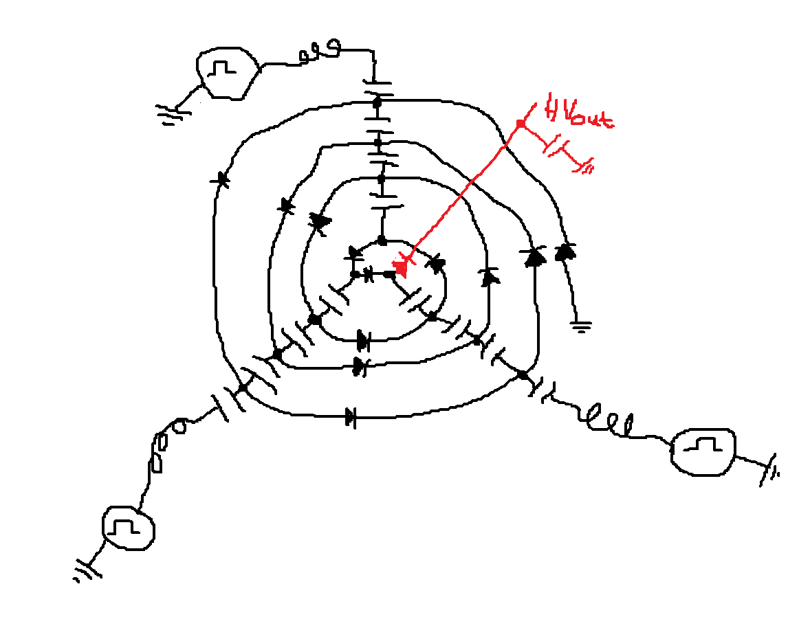 |
| Spiral style schematic of the nixie multiplier, it has a filtering peak detector on the output. |
This spiral topology represents a combo of two basic multiplier types the parallel and series style multipliers. Each 'spoke' coming from the center of the spiral is topologically identical to a capacitor string (or stack) found in a series multiplier while each round of the spiral is analogous to travelling up a parallel multiplier. The spiral multiplier of some arbitrary number of rounds $ \geq 1$ and spokes $ \geq 2$ is a generalization of the series and parallel multipliers where either one represents a base case; spiral circuits similar to the full wave cockcroft-walton multiplier can also be constructed (look at the wikipedia page).
Backing up to the big picture:
Diode based voltage multipliers have been around a very long time like almost a 100ish years according to the wikipedia. If you aren't familiar with voltage multipliers they do as the name implies and take a smaller magnitude (AC) voltage and turn it into a larger magnitude (DC) voltage of some multiple of the AC amplitude (in the ideal case).
Fundamentally multipliers are built up of capacitor coupled nodes with some diodes slapped on. This forms a network of peak detectors, each peak detector takes the peak AC voltage through a diode and deposits it on to a capacitor. This forms a 'unit pump':
 |
| The unit cell of a multiplier |
In the unit pump, if $Vac$ dips below $Vin$ (by a diode drop), charge is deposited onto capacitor C1. $Vo = Vin-Vd$ when Vac swings positive you get: $\hat{Vo} = \hat{Vac} + Vc$. The capacitor maintains a DC bias from the AC wave form injected through Vac boosting Vo.
These unit pumps are chained in various formats to form different types of multipliers.
A series multiplier is driven from a power source a coupled up through all the subsequent stages whereas in a parallel multiplier the power source is directly coupled through a capacitor to a node in a chain of diodes. The difference in the power coupling has interesting effects. The source impedance of a series multiplier increases as the cube of the number of stages; this is an incredible pain sometimes. However it conveniently grades the voltage up the whole multiplier stack so you only have to couple power into the low voltage end and all of your components can be of a lower voltage rating.
 |
| Series multiplier, takes 20Vpp input, 40Vmax output |
A parallel multiplier doesn't have that $n^{3}$ impedance issue but requires direct energy couplings to the high voltage end resulting in a fair amount of energy storage (for the same F capacitors) and it doesn't grade the voltage with the capacitors. Note the similarity between the above series example and the below parallel example
 |
| Parallel multiplier, takes 20Vpp input, 40Vmax output |
The voltage increases by the Vpp AC voltage with every pumping node and gets filtered to some extent by every filtering node. Both multipliers have the same AC source and reach the similar output voltage.
Both are special in their own way. However both also only represent usage of the unit pump in one 'dimension'. The spiral multiplier is the cross of the two defining a a series/parallel matrix of unit cells. I haven't actually analyzed the topology in detail to see if there are any fundamentally better properties, but it seems like a fun experiment. Analytical awesomeness can be postponed.
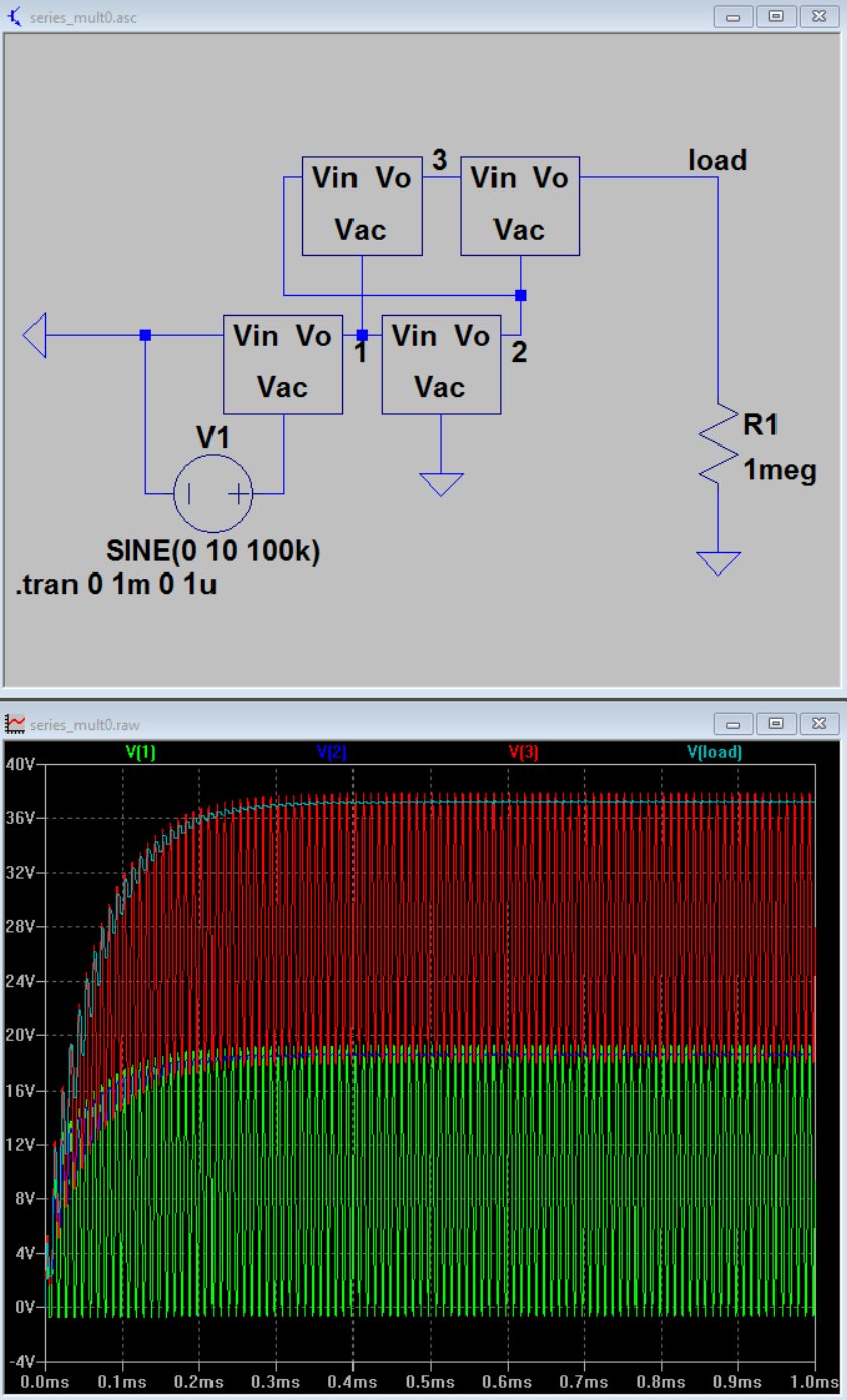
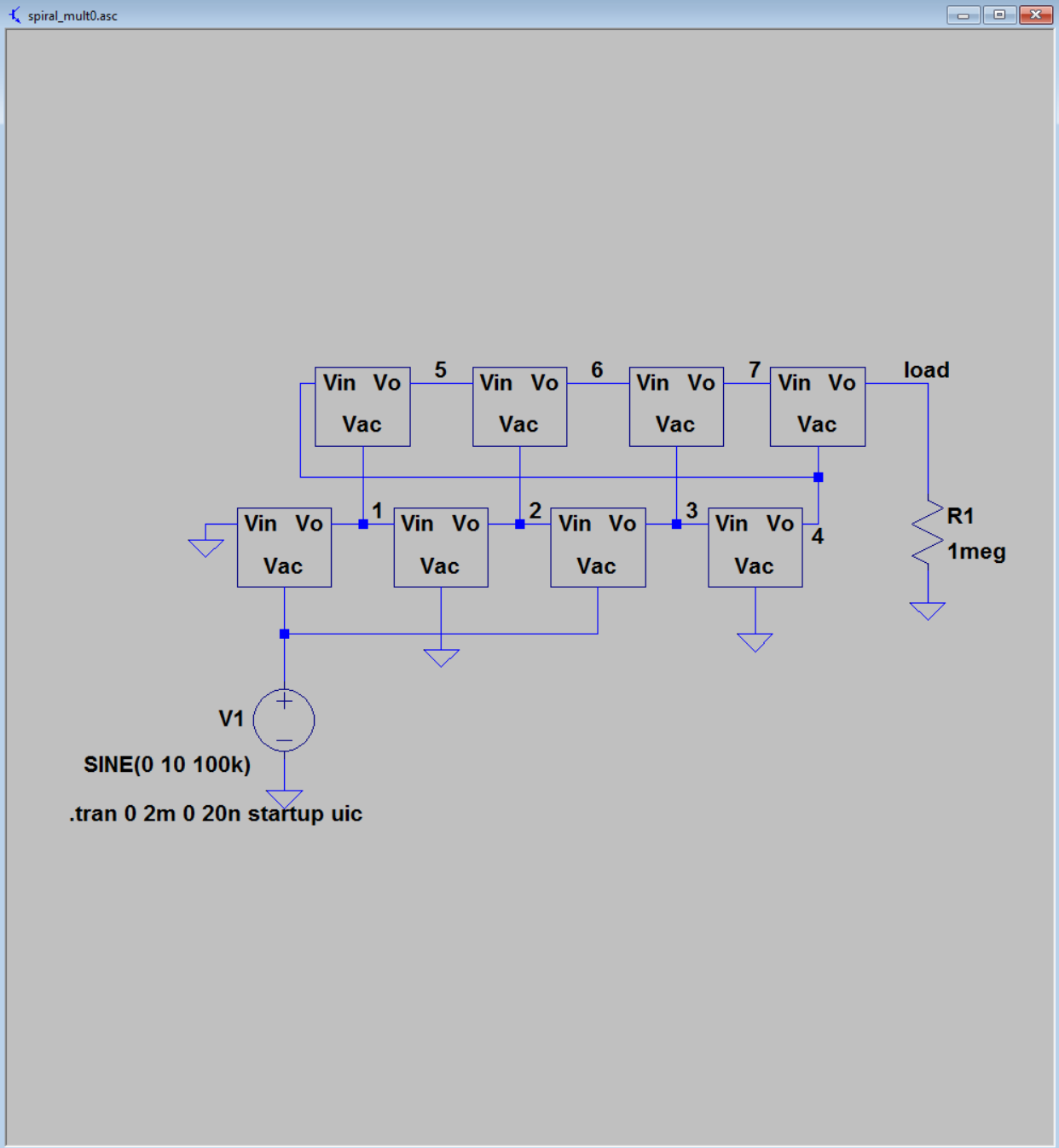 |
| A 2x4 Spiral Multiplier |
 |
| 2x4 Wave forms with tiny load |
Here is an example of a spiral multiplier.It is effectively 2 parallel multipliers (each consisting of 4 unit cells) stacked on top of each other. The output of the lower one feeding the input of the higher voltage one. Really you could string $n$ of them together on top of each other and feed the bias of each multiplier one into the beginning of the next. Alternately it can be seen as taking $M$ series capacitor strings and setting them side by side, linking up each DC biased section in the proper format. 2 rounds of a 4 spoke spiral. How it is viewed is a somewhat arbitrary exercise imo. that could be argued multiple ways depending on the nuances of a particular system. Every circuit is what it does. Note that in the initial 4x3 multiplier at the top of the post I didn't even bother with a filter string in the body of the multiplier, just an output peak detector to mellow the output ripple.
I'm tired of typing about this right now and feel like it'll turn into a thesis if I keep going. The spiral multiplier concept seemed like an interesting one and there are a couple expansions of the topology that I can think of, involving peak detector loops over filter caps and gaming the phasing of the pump sources.
toodloo
Keep sharing such a valuable information. Thanks
ReplyDeletePower transformers in India | Transformer manufacturer in India